
Circuit Breaker: Working Principle, Types and Structure

What is a Circuit Breaker
Catalog
| |
| |
I Working Principle
The circuit breaker is generally composed of a contact system, an arc extinguishing system, an operating mechanism, a trip unit, and housing.
When there is a short circuit, the magnetic field generated by a large current (generally 10 to 12 times) overcomes the reaction spring, the trip unit pulls the operating mechanism, and the switch trips instantaneously. When the circuit is overloaded, the current becomes larger, the heat generation is increased, and the bimetallic sheet deforms to a certain extent to push the mechanism to move (the greater the current, the shorter the operating time).
The high-voltage circuit breaker must break the arc of 1500V and 1500-2000A. These arcs can be stretched to 2m and continue to burn without extinguishing. Therefore, arc extinction is an urgent problem for high voltage circuit breakers.

Figure 1. Arc Extinction
The principle of arc blowing and arc extinguishing is mainly to reduce the thermal dissipation of the cooling arc. On the other hand, the lengthening of the arc is used to strengthen the recombination and diffusion of the charged particles. At the same time, the charged particles in the arc gap are blown away, and the dielectric strength of the medium is quickly restored.
Low-voltage circuit breakers, also called automatic air switches, can be used to connect and disconnect load circuits, and can also be used to control motors that start infrequently. Its function is equivalent to the sum of some or all of electrical systems such as knife switch, overcurrent relay, no-voltage relay, thermal relay, and leakage protector, which is an important protection appliance in low voltage distribution network.
Low-voltage circuit breakers have a variety of protection functions (overload, short circuit, undervoltage protection, etc.). Also, it has an adjustable operating value, high breaking capacity and easy and safe operation, so they are widely used.
The low-voltage circuit breaker is composed of operating mechanism, contacts, protection devices (various trip units), and arc extinguishing systems. Its main contact is manually operated or electrically closed. After the main contact is closed, the free tripping device locks the main contact in the closing position.
The coil of the overcurrent trip unit and the thermal element of the thermal trip unit is connected in series with the main circuit, while the coil of the undervoltage trip unit is connected in parallel with the power supply.
When the circuit is short-circuited or severely overloaded, the armature of the overcurrent tripping device pulls in, causing the free tripping device to operate, then the main contact disconnects the main circuit. When the circuit is overloaded, the thermal element of the thermal trip unit heats up and bends the bimetal sheet, pushing the free tripping mechanism to move. When the circuit is undervoltage, the armature of the undervoltage trip unit trips, activating the free trip mechanism.
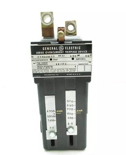
Figure 2. Over-current Tripping Device
The shunt trip unit is used for remote control. During normal operation, the coil is powered off. When distance control is required, we need to press the start button to energize the coil.
II Working Conditions
1. Ambient Temperature
Upper limit: 40℃;
Lower limit: -5℃;
Average value within 24h: < 35℃.
2. Altitude
The altitude of the installation site does not exceed 2000m.
3. Atmospheric Conditions
The relative humidity of the atmosphere does not exceed 50% when the ambient air temperature is 40℃. It can have a higher relative humidity at a lower temperature. The monthly average maximum relative humidity of the wettest month is 90%, and the average monthly minimum temperature of the month is 25℃. Besides, we should also consider the condensation that occurs on the product surface due to temperature changes.
4. Pollution level: level 3
5. Control Circuit
(1) The integrity of the protection device and the tripping and closing circuits in the control circuit should be monitored to ensure the normal operation of the circuit breaker.
(2) The position status of the normal closing and opening of the circuit breaker should be indicated, and there should be an obvious indicator signal during automatic closing and automatic tripping.
(3) After the closing and tripping are completed, the command pulse should be tripped, to cut off the power supply of closing or tripping.
(4) When there is no mechanical anti-trip device, an electrical anti-trip device should be installed;

Figure 3. Electrical Anti-trip Device
(5) The accident tripping signal circuit of the circuit breaker should be wired according to the "non-correspondence principle".
(6) For equipment that may have abnormal working conditions or malfunctions, a warning signal should be installed.
(7) The power supply of the spring operation mechanism and manual operation mechanism can be DC or AC, and the power supply of the electromagnetic operation mechanism should be DC.
III Circuit Breaker Properties
The characteristics of the circuit breaker are:
1. Rated operating voltage (Ue)
The voltage at which the circuit breaker operates under normal (uninterrupted) conditions.
2. Rated Current (In)
The maximum current value that a circuit breaker equipped with a special overcurrent trip relay can withstand at the ambient temperature specified by the manufacturer, and will not exceed the temperature limit specified by the current bearing component.
3. Short-circuit Relay Tripping Current(Im)
Short-circuit tripping relay (instantaneous or short-time delay) is used to quickly trip the circuit breaker when the high fault current appears, and its trip limit is the setting value lm.
4. Rated Short-circuit Breaking Capacity (Icu or Icn)
The rated short-circuit breaking current of the circuit breaker is the highest (expected) current value that the circuit breaker can break without being damaged. The standard current value is the root-mean-square value of the AC component of the fault current, and the DC transient component (which always occurs under short circuit) is assumed to be zero. The rated value of industrial circuit breaker(Icu) and household circuit breaker(Icn) are usually given in kA root mean square.
5. Short-circuit Breaking Capacity (Ics)
The rated breaking capacity of the circuit breaker is divided into two types: rated limit short-circuit breaking capacity and rated operating short-circuit breaking capacity.
No matter what kind of circuit breaker it is, it'll have the two important technical indicators of Icu and Ics. However, as the circuit breaker used on the branch line, it would be sufficient to meet the Icu.
Some people prefer to choose a larger value. However, if it is too large, it will cause unnecessary waste. For example, for the same type of circuit breaker, the price of the H type一high breaking type一is 1.3 times to 1.8 times more expensive than the S type一ordinary type). Therefore, it is not necessary to blindly pursue the best Icu.
On the contrary, for circuit breakers used on the main line, the requirements of the Icu and Ics should both be satisfied. If only the Icu is used to measure the breaking capacity, there will be some hidden dangers.
IV Circuit Breaker Types
There are many types of circuit breakers, and can be classified according to usage, structure form, operation method, pole number, installation method, arc extinguishing medium, and application.
According to... | Types |
using category | non-selective type(type A) & selective type(type B) |
structure | universal type and plastic shell type |
operation mode | manual operation type and non-manual operation (electric, energy storage)type |
number of poles | monopole, two-pole, three-pole, and four-pole type |
installation method | fixed type, plug-in type and drawer type |
arc extinguishing medium | air type and vacuum type |
arc-extinguishing technology | arc-extinguishing and current-limiting type |
usage | types used for power distribution, motor protection, household, residual current (leakage) protection, special use, etc. |
V Circuit Breaker Structure
1. Internal Accessories
(1) Auxiliary Contact
The auxiliary contact is contact between the opening and closing mechanism of the main circuit, mainly used for the display of the opening and closing status of the circuit breaker. It is connected to the control circuit to control or interlock its related electrical appliances through the opening and closing of the circuit breaker, like outputting signals to signal lights, relays, etc.
For molded case circuit breaker(MCCB) with a shell frame rated current(lnm) of 100A, it has a single breakpoint conversion circuit, and the one with 225A lnm and above has a bridge contact structure, and the conventional thermal current is 3A. Also, one with a 400A lnm and above can be installed with two usually open and two usually closed contacts, and the conventional thermal current is 6A. The number of operational performance is the same as the total number of circuit breaker operation performance.
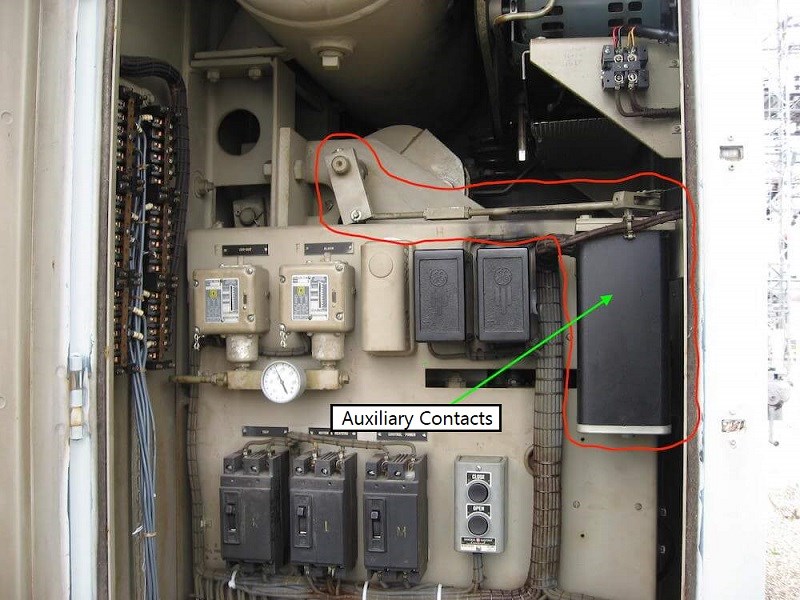
Figure 4. A Bank of Auxiliary Contacts in Oil Circuit Breaker
(2) Alarm Contact
The alarm contact is mainly used for the circuit breaker accident, and it will only act when the circuit breaker trips and breaks. When there is an overload, short circuit or undervoltage fault on the load of the circuit breaker, the circuit breaker will trip freely, and the alarm contact will move from the original open position to the closed position, switching on the indicator, electric bell, buzzer, etc. in the auxiliary line to display the fault trip status.
Since it's quite rare that a circuit breaker tripping freely due to a load failure, the life of the alarm contact is 1/10 of the life of the circuit breaker. The working current of the alarm contact generally does not exceed 1A.
(3) Shunt Trip
A shunt trip is a trip that is excited by a voltage source, whose voltage is independent of the main circuit voltage. It is an accessory for remote control of opening. When the power supply voltage is equal to any voltage between 70%-110% of the rated control power supply voltage, the circuit breaker can be reliably broken.
The shunt trip has a short-time working system, and the coil conduction time should generally not exceed 1S, otherwise, the wire will be burned. In order to prevent the coil from burning, a microswitch is connected in series with the shunt trip coil. When the shunt trip is pulled in by the armature, the microswitch is switched from normally closed to normally open.
Due to the power and control circuit of the shunt trip is cut off, even if the button is manually pressed, the shunt coil will never power on. This avoids the occurrence of coil burnout. When the circuit breaker is closed again, the microswitch is in the normally closed position again.
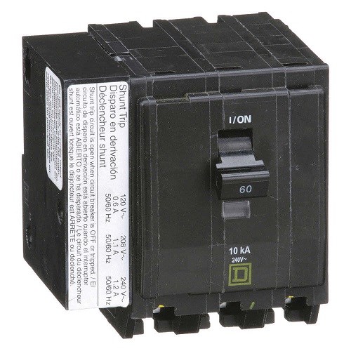
Figure 5. Shunt Trip Circuit Breaker
(4) Under-voltage Trip
An under-voltage trip is a type of trip that allows the circuit breaker to be opened with delay or without delay when its terminal voltage drops to a specified range. It operates when the power supply voltage drops (even slowly) to the range of 70% to 35% of the rated operating voltage.
When the power supply voltage is equal to 35% of the rated operating voltage of the trip, the under-voltage trip should be able to prevent the circuit breaker from closing; when the power supply voltage is equal to or greater than 85% of the rated operating voltage, it should be able to ensure the circuit breaker is reliably closed under hot conditions. Therefore, when a certain voltage drop occurs in the power supply voltage in the protected circuit, the circuit breaker can be automatically cut off, so that the load electrical appliances or equipment below the circuit breaker are protected from under-voltage damage.
When in use, the under-voltage trip coil is connected to the power supply side of the circuit breaker, and the circuit breaker can only be closed after the under-voltage trip is on.
2. External Accessories
(1) Electric Operating Mechanism
This is an accessory for long-distance automatic opening and closing circuit breakers, which includes motor operating mechanism and electromagnet operating mechanism.
The motor operating mechanism is a moulded case circuit breaker with lnm of 400A and above, the electromagnet operating mechanism is suitable for moulded case circuit breaker with lnm of 225A and below. Whether it is an electromagnet or motor, their pull-in and rotation directions are the same, only by the position of the cam inside the electric operating mechanism to achieve closing and opening. When the circuit breaker is operated by the electric mechanism, the circuit breaker should be able to close at any voltage between 85% and 110% of the rated control voltage.
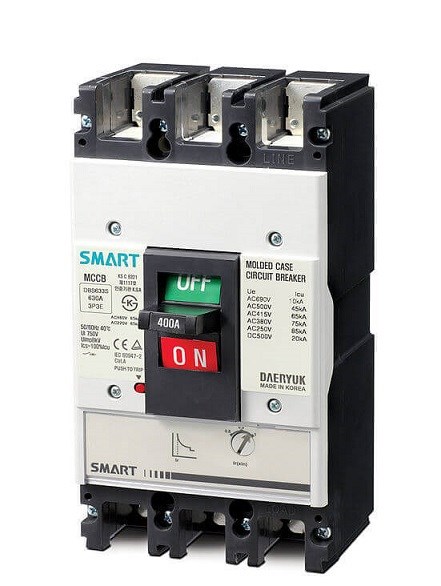
Figure 6. Moulded Case Circuit Breaker
(2) Rotation Handle
It's suitable for molded case circuit breakers. A mechanism for the rotation handle is installed on the cover of the circuit breaker. The rotary shaft of the handle is installed in its mechanism matching hole. The other end of the rotary shaft passes through the door hole of the drawer cabinet, and the handle is mounted on the shaft head exposed on the door of the complete device, of which the round or square base is fixed on the door with screws.
This installation enables the operator to rotate the handle clockwise or counterclockwise outside the door to ensure the closing or opening of the circuit breaker. At the same time, turning the handle can ensure that the cabinet door closed when the circuit breaker is closed until the turning handle is opened or re-trip. In an emergency, when the circuit breaker is "closed" and the electrical panel needs to be opened, we can press the red release button on the side of the handle base.
(3) Extension Handle
It is an external extension handle, which is directly mounted on the handle of the circuit breaker. It is generally used for large-capacity circuit breakers of 600A and above for manual opening and closing operations.
(4) Handle Locking Device
The clip is installed on the handle frame, and the handle is punched and then locked with a padlock. When the circuit breaker is closed, the handle locking device can stop others to cut the power off and cause a failure. Also, when the load side of the circuit breaker needs to be repaired or power is not allowed, it can prevent the circuit breaker from being mistakenly closed.
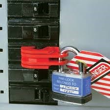
Figure 7. Circuit Breaker Locking Device
VI Wiring Method
The wiring method of the circuit breaker is wiring in front of the board, behind the board, plug-in type, drawer type, among which wiring in front of the board is the most common wiring method.
1. Wiring behind the Board
The biggest feature of the wiring behind the board is that the circuit breaker can be replaced or repaired without rewiring, only by disconnecting the pre-stage power supply.
Due to the special structure, the product has been equipped with special mounting plates, mounting screws, and wiring screws according to the design requirements. It should be noted that the reliability of the contact of the large-capacity circuit breaker will directly affect the normal use of the circuit breaker, so we must install it strictly according to the requirements of the manufacturer.
2. Plug-in Wiring
On the installation board of the complete device, first, install a circuit breaker mounting base with 6 sockets on it. There is a connecting plate on the surface of the mounting base or bolts behind the mounting base, and the power cord and load line are connected to the mounting base in advance.
When in use, insert the circuit breaker directly into the mount. If the circuit breaker is broken, just pull out the broken one and replace it with a good one. The replacement time of the plug-in wiring is shorter than wiring before and behind the board, which is more convenient.
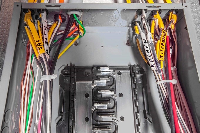
Figure 8. Wiring in Circuit Breaker
3. Drawer-type Wiring
The circuit breaker's entrance and exit drawers are rotated clockwise or counterclockwise by the rocker. Both the main circuit and the secondary circuit use a plug-in structure, omitting the isolator necessary for a fixed type. One machine with two usages is more economical, and at the same time brings great convenience to operation and maintenance, increasing safety and reliability. In particular, the main circuit contact holder of the drawer base can be used interchangeably with the contact holder of the NT-type fuse breaker.
Latest Electronic Blog:
 UTMEL
UTMEL
We are the professional distributor of electronic components, providing a large variety of products to save you a lot of time, effort, and cost with our efficient self-customized service. careful order preparation fast delivery service
1.What is a circuit breaker and how does it work?
Circuit breakers act as resettable fuses . These are automatically operated electrical switches that protect electrical circuits from overloading or short circuiting. They detect faults and then stop the flow of electricity.
2.What is called circuit breaker?
A circuit breaker is an automatically operated electrical switch designed to protect an electrical circuit from damage caused by excess current from an overload or short circuit. Its basic function is to interrupt current flow after a fault is detected.
3.What happens when a circuit breaker trips?
When it is said that a circuit breaker “trips,” it means that circuit has detected what's known as a fault condition and has shut itself off to prevent the wiring from overheating and potentially igniting itself.
4.What is the purpose of a circuit breaker?
A circuit breaker is an electrical switch designed to protect an electrical circuit from damage caused by overcurrent/overload or short circuit. Its basic function is to interrupt current flow after protective relays detect a fault.
5.What are the types of circuit breaker?
There are three basic circuit breaker varieties: standard breakers (which include both single-pole and double-pole circuit breakers), ground fault circuit interrupter circuit breakers (GFCIs) and arc fault circuit interrupter circuit breakers (AFCIs).
 What is Surge?UTMEL09 February 20225602
Hello everyone, I am Rose. Today I will introduce surge to you. Surge is an overvoltage that occurs suddenly and surpasses the typical operating voltage. A surge is a brief wave of current, voltage, or power in a circuit, in general.
Read More?") What is a Surge Protection Device (SPD)?UTMEL22 June 202125935
What is a Surge Protection Device (SPD)?UTMEL22 June 202125935A surge protection device (SPD), also called a surge protector, is an electronic device that provides safety protection for various electronic equipment, instruments, and communication lines. When a spike current or voltage is suddenly generated in the electrical circuit or communication circuit due to external interference, the surge protection device can conduct and shunt in a very short time, so as to prevent the surge from damaging other equipment in the circuit.
Read More What is a Ground Fault Circuit Interrupter?UTMEL27 March 20254535
A ground fault circuit interrupter(GFCI) is an electrical device installed to protect against severe electric shocks. It can also reduce electrocutions, minimize electrical burns and shock injuries, and detect ground faults, and interrupts the flow of electric current.
Read More What is Vacuum Circuit Breaker?UTMEL12 October 20217963
Hello, I am Rose. Welcome to the new post today. The name "vacuum circuit breaker" comes from the fact that both the arc extinguishing medium and the insulating medium of the contact gap after arc extinguishing are high vacuum; it has the advantages of compact size, light weight, frequent operation, and no arc extinguishing maintenance. This article introduces basis knowledge about vacuum circuit breaker.
Read More Circuit Breaker: Working Principle, Types and StructureUTMEL04 August 202010201
Circuit breaker is a switching device capable of closing, carrying and breaking the current under normal and abnormal circuit conditions within a specified time. So what's its structure and how many types are there? How does it work? Read this.
Read More
Subscribe to Utmel !
![BZT52C13T/R13]() BZT52C13T/R13
BZT52C13T/R13Panjit
![SR29T/R13]() SR29T/R13
SR29T/R13Panjit
![1N3673A]() 1N3673A
1N3673AMOTOROLA
![GP10-4007/3]() GP10-4007/3
GP10-4007/3Vishay
![R6200430XXOO]() R6200430XXOO
R6200430XXOOMicrochip
![DD800S17K6C_B2]() DD800S17K6C_B2
DD800S17K6C_B2Infineon Eupec
![BUK961255B118]()
![BZW04-85BHR0]() BZW04-85BHR0
BZW04-85BHR0Taiwan Semiconductor
![BZW06-299 R0]() BZW06-299 R0
BZW06-299 R0Taiwan Semiconductor
![BZX55B13T/R]() BZX55B13T/R
BZX55B13T/RPanjit
